 RC
RCFlySky FS-i6 → RCForge#
This guide covers the original FS-i6, a classic ATmega328P Uno R3 or Nano, and either a wired trainer connection or a separate bound receiver. The receiver model and your cable pinout still need to be checked. FS-i6X/i6S, Uno R4 and Nano Every have different hardware.
Start with the visual connection guide for illustrated wiring, controller diagrams and a configurable AI-agent setup prompt. This page is the detailed reference.
Hardware status: direct trainer PPM reception has been demonstrated in user-supplied Nano diagnostics. Receiver PPM and PWM connections are still to be tested successfully. See the connection test status for evidence and unresolved checks.
Choose a connection#
| Path | What you need | RCForge connection |
|---|---|---|
| Transmitter → simulator adapter → USB | FS-i6-compatible trainer/PPM-to-USB joystick adapter, such as the appropriate FS-SM100 kit | Controllers → RC transmitter → Find USB adapter |
| Transmitter → Arduino → USB | Verified trainer PPM OUT breakout, Uno/Nano, resistors, USB data cable | Controllers → RC transmitter → Connect Arduino |
| Transmitter → receiver → Arduino → USB | Bound receiver with PPM output, or six PWM channel outputs; Uno/Nano and jumpers | Controllers → RC transmitter → Connect Arduino |
A firmware-update cable is not a simulator adapter. FlySky describes both transmitter and receiver PPM simulator connections in its simulator FAQ, question 34.
The Arduino route uses the board's normal USB serial connection. It does not turn a classic Nano/Uno into an operating-system joystick or require flashing its USB interface. RCForge now reads that serial stream directly. Other simulators will not automatically see this sketch as a gamepad. See the official Uno R3 and classic Nano hardware documentation.
Use desktop Chrome at http://127.0.0.1:5180 (or HTTPS). Click Connect Arduino and select the board's USB serial port. Web Serial needs browser support and a user-initiated device chooser; RCForge displays a compatibility message when unavailable. Embedded browsers may restrict it even when based on Chromium. Close Arduino Serial Monitor before connecting. Chrome Web Serial documentation.
Parts and wiring rules#
For either Arduino board: a USB data cable, jumper leads, a breadboard, one 1 kΩ series resistor and one 47 kΩ pulldown for each signal input. PPM needs one signal; six-channel PWM needs six. Use a separate receiver on the bench with no servos, ESCs or motors attached.
- Power the Arduino from USB. Power the transmitter from its own batteries.
- Connect signal grounds together. Never connect transmitter battery/VCC to an Arduino signal pin or USB 5 V rail.
- Use receiver pins marked S / + / −, matching the receiver label; wire colors and connector orientation are not proof of pin order.
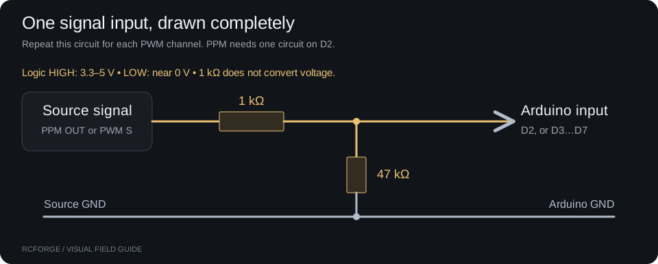
- The input circuit here expects a nonnegative logic signal with LOW near 0 V and HIGH between 3.3 V and 5 V. Check unknown trainer cables with a scope/logic analyzer and suitable probes before connecting them. A 1 kΩ resistor is not a voltage converter; use a suitable level translator if the signal exceeds 5 V or goes negative.
- Power a bare receiver from Arduino 5V, not VIN or 3V3, only if its documented supply range includes 5 V and its current draw fits the board/USB supply. The FS-iA6B is specified for 4.0–8.4 V. Do not connect an ESC/BEC or another supply simultaneously to that receiver power rail. Other receivers must be checked separately. FlySky FS-iA6B specifications.
Input conditioning, repeated per connected signal:
A. Directly from the transmitter#
Using a simulator adapter#
- Use an adapter explicitly compatible with the FS-i6 rear trainer connector and documented to expose a USB joystick. Do not use an update/programming cable.
- Connect the transmitter's trainer output to the adapter, then connect the adapter to USB. Power on the transmitter.
- Create a dedicated simulator airplane model with channel mixing disabled. Follow the adapter's instructions for any trainer/student output setting.
- In RCForge choose Controllers → RC transmitter → Find USB adapter. Select the USB controller and calibrate as below. This route does not use the Arduino sketch or Connect Arduino button.
Using your Uno or Nano#
Use a trainer breakout whose PPM OUT and GND contacts have been identified for the original FS-i6. Connect as follows:
| Verified trainer connection | Arduino |
|---|---|
| PPM OUT from transmitter | D2, through the conditioning circuit above |
| GND | GND |
| PPM IN, VCC, unused contacts | Leave unconnected |
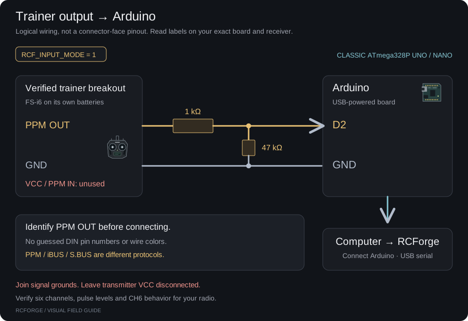
Connector limitation: the manufacturer resources checked identify the trainer/update interface but do not establish the numbered PPM-out pinout for your particular plug/breakout. This guide deliberately uses signal names. A solder-side diagram can mirror a socket/front-view diagram; generic mini-DIN drawings and internet wire colors are insufficient. Use a documented FS-i6 PPM-out breakout, or identify it with the cable's manufacturer pinout and measurement. If you do not have that information, use the receiver path below, which uses labeled receiver pins.
Select RCF_INPUT_MODE 1 in the sketch. It reads six-channel PPM from successive rising edges. The PPM frame must have six channel intervals of 800–2200 μs and a sync gap over 3000 μs. If your firmware sends a different channel count, this default intentionally rejects it; configure/verify six-channel output before use. Enable the transmitter's appropriate student/output mode if its firmware requires it; trainer PPM input is not the signal to read. Confirm the actual output before changing code.
The default CH6 RUN guard described below also applies to this wired path. Student mode bypasses transmitter settings, so an auxiliary switch assignment may not be applied; verify which physical control is actually sent as CH6. For a wired trainer-only setup with no usable CH6 control, you may set RCF_GUARD_CHANNEL 0: pulse-loss detection still applies, but there is no receiver RF failsafe to monitor. Do not carry that configuration over to a wireless receiver without revisiting its failsafe. Turning the transmitter off or unplugging its signal should stop pulses and pause the simulator. FS-i6 manual, section 7.7.
B. Via the receiver: PPM, fewer wires#
Use this when your bound receiver provides a labeled PPM or PPM/CH1 output, for example an FS-iA6B configured for PPM. In the FS-i6 menu, open System Setup → RX setup → PPM Output and select PPM; hold CANCEL to save. Menu wording varies with firmware. Confirm that this is PPM on CH1, not ordinary CH1 PWM. FS-i6 manual, section 8.2.
| Receiver pin | Arduino |
|---|---|
| PPM / CH1 S, configured as PPM | D2 through 1 kΩ; 47 kΩ from D2 to GND |
| Receiver − | GND |
| Receiver +, only when rated for 5 V | 5V (USB-powered board, bare receiver only) |
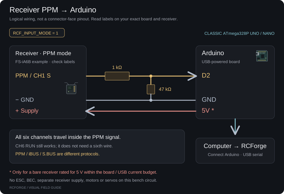
Select RCF_INPUT_MODE 1. A port marked i-BUS SERVO, SENS, or S.BUS is not PPM and cannot be fed into this decoder. This sketch does not decode those protocols. Use the receiver's PPM output or the PWM path below.
C. Via the receiver: six PWM channels#
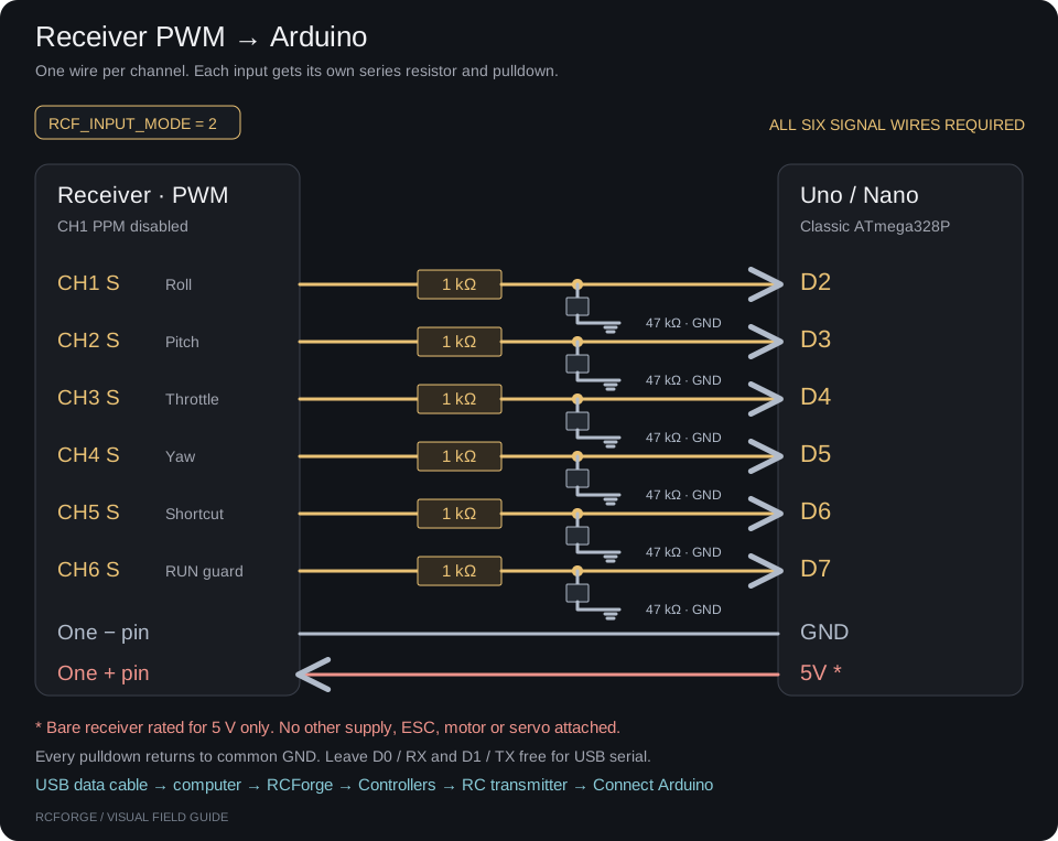
Use this for a receiver with normal CH1–CH6 servo outputs, including a PWM-only receiver. Disable PPM on CH1 if it had been enabled.
| Receiver signal pin | Arduino digital pin | Starting assignment |
|---|---|---|
| CH1 S | D2 | Roll / aileron |
| CH2 S | D3 | Pitch / elevator |
| CH3 S | D4 | Throttle |
| CH4 S | D5 | Yaw / rudder |
| CH5 S | D6 | Optional switch for a simulator shortcut |
| CH6 S | D7 | RUN guard / receiver failsafe |
| One receiver − | GND | Common ground |
| One receiver +, rated for 5 V | 5V | Receiver power; no other power source attached |
Add the series resistor and pulldown to each signal input. Connect all six signal channels; a missing channel makes the default sketch report invalid input. Select RCF_INPUT_MODE 2.
The sketch captures edges with pin-change interrupts. It does not read channels sequentially with blocking pulseIn(), so simultaneous receiver pulses can be measured. Leave D0/RX and D1/TX free for USB serial. No external Arduino libraries are needed.
Configure the radio and the RUN guard#
- Create a dedicated ordinary airplane model named RCForge. Disable V-tail, elevon and other mixing. Begin with centered trims and conventional endpoints; the simulated aircraft performs its own mixing.
- In auxiliary-channel setup assign CH6 to a two-position switch. Choose a convenient high position as RUN: its pulse must exceed 1700 μs. The low position is STOP. CH5 remains available for a separate simulator shortcut.
- For a wireless receiver, set its failsafe CH6 low, throttle low, and centered flight controls. On the documented FS-i6 menu, open RX setup → Failsafe, select CH6, enable its failsafe, move its switch to STOP and hold CANCEL to confirm. Hold CANCEL again to save the overall menu. Repeat for throttle low and centered controls. A failsafe value of Off means hold the last value; it does not mean zero throttle. Verify your receiver implements the settings. FS-i6 manual, section 8.4.
- In RUN, the Arduino built-in LED is on only when all six channels have valid, fresh pulses. In STOP it is off and RCForge pauses. Restoring RUN makes input available but does not automatically resume flight.
- Test RF loss: while receiving live input, turn the transmitter off. RCForge must lose live input and pause. Turn it on, verify low throttle, then resume manually.
Fresh receiver pulses do not prove a live radio link. Some receivers continue transmitting held or configured failsafe values after RF loss. The guard detects that loss only if your receiver actually drives CH6 low (or stops pulses). If the radio-off test leaves RCForge live, the failsafe configuration is not verified; do not rely on automatic RF-loss detection. The same issue is documented for iBUS by the IBusBM project's author.
The sketch defaults to #define RCF_GUARD_CHANNEL 6. Setting it to 0 removes this guard, leaving only missing/invalid pulse and USB timeout detection. Use that only for the wired trainer exception above or a deliberate diagnostic session; it cannot detect a receiver repeating held channels. Keep CH6 reserved rather than mapping it to restart/start. No receiver telemetry or RF link-quality flag is decoded here.
Upload the sketch#
File: hardware/rcforge_bridge/rcforge_bridge.ino. The same file supports both boards and all three Arduino wiring paths above.
- Open it in Arduino IDE. Keep it inside a folder named
rcforge_bridge. - Set
RCF_INPUT_MODEnear the top: 1 for PPM or 2 for six PWM wires. Leave the CH6 guard enabled. - Select Arduino AVR Boards → Arduino Uno, or Arduino Nano → ATmega328P. This code deliberately rejects non-ATmega328P targets.
- Select the board's USB port and upload. Some classic Nano boards need ATmega328P (Old Bootloader). Use the board's actual bootloader; see Arduino's Nano processor guide.
- Optionally open Serial Monitor at 115200 baud. Lines beginning
RCF1confirm the sketch is running;...,1,PPM,...or...,1,PWM,...indicates accepted input. A0status means invalid/missing input or guard STOP. Close Serial Monitor afterward. - Open RCForge and choose Controllers → RC transmitter → Connect Arduino. Choose the Arduino port, allow its reboot time, then set the RUN switch high. The selected device should become
RCForge Arduino PPM (...)orRCForge Arduino PWM (...).
CLI alternative after installing Arduino CLI:
arduino-cli core install arduino:avr
arduino-cli board list

# Compile PPM for Uno (default mode)
arduino-cli compile --fqbn arduino:avr:uno hardware/rcforge_bridge

# Compile PWM for classic Nano without changing the source default
arduino-cli compile --fqbn arduino:avr:nano:cpu=atmega328 \
  --build-property compiler.cpp.extra_flags=-DRCF_INPUT_MODE=2 \
  hardware/rcforge_bridge

# Upload the same mode and board; replace YOUR_PORT with board list's port.
arduino-cli compile --upload --port YOUR_PORT \
  --fqbn arduino:avr:nano:cpu=atmega328 \
  --build-property compiler.cpp.extra_flags=-DRCF_INPUT_MODE=2 \
  hardware/rcforge_bridge
Calibrate and use the controls#
The Arduino sends channels in receiver order. RC transmitter defaults in RCForge are roll Axis 1, pitch Axis 2, throttle Axis 3, yaw Axis 4. Verify with the live transmitter drawing; never assume direction from the channel number alone.
- Move one stick at a time. Use Detect or the axis selector if the order differs. Reverse any channel that moves the wrong way.
- Under Calibration, center roll/pitch/yaw and capture neutral. Start travel capture and move every flight control through its complete range, including throttle low/high. Save setup.
- Check roll/pitch/yaw return near zero and throttle reaches 0–100%. On Mode 2, pulling the right stick back should command nose-up; left stick vertical should command throttle. Match the directions shown in RCForge's live display.
- Keep transmitter expo and RCForge expo from being applied twice. In Aircraft trim & profile files, set elevator trim to zero if you want all trim supplied by the transmitter.
- Under Shortcuts, an unused CH5 appears as Axis 5 and can trigger an action at one endpoint. Select its positive/negative endpoint for Start/pause or Restart. Return it before triggering again. The transmitter's menu keys are not transmitted as channels.
- Return to Fly, check throttle, and start deliberately. After any interruption, inputs can reconnect but flight remains paused until you resume.
Calibration is saved in this browser under the device ID. The serial ID includes mode and USB vendor/product IDs, not an individual board serial number. Two identical boards may share a profile; recalibrate when swapping receivers, radios, endpoints or identical boards.
What the bridge checks#
- Arduino rejects incomplete PPM frames, malformed pulse widths, and any required channel stale for over 100 ms. It sends a status flag every 20 ms.
- RCForge validates framing, channel count, pulse ranges, sequence progression and CRC. Corruption and duplicate packets cannot refresh input. No usable packet for over 250 ms removes the input device and pauses a flight using it at the next update.
- Invalid input removes the device immediately when its status packet is processed. Other connected gamepads are not silently selected in its place.
- No background auto-resume. Signal return, reconnect and switch movement must be followed by a deliberate start/resume action.
- This is simulator input software, not an aircraft flight controller or safety-rated radio failsafe. It measures channel pulses, not radio latency, RSSI, battery telemetry or actual servo motion.
Serial protocol#
The transport is board-independent: another Arduino or microcontroller can work by implementing this protocol over USB serial. The included sketch is specific to classic ATmega328P Uno/Nano boards. See using another Arduino for the requirements.
Wire format (developer reference): RCF1,sequence,valid,mode,count,pulse1,...,pulseN*CRC\r\n. Sequence is unsigned 16-bit with wraparound; valid is 0/1; mode is PPM/PWM; pulses are integer μs. CRC is four hex digits of CRC-16/CCITT-FALSE (polynomial 0x1021, initial 0xFFFF, no reflection/final XOR), calculated over the ASCII text before *. Firmware sends six channels. Browser decoder accepts 4–8 for future bridges. Resetting the board mid-connection can reset sequence numbers; use Disconnect then Connect Arduino to start a new session.
Troubleshooting#
| Symptom | Check |
|---|---|
| No Arduino in chooser | USB data cable, correct port, OS driver for the exact board/USB chip. Do not select Bluetooth or unrelated serial devices. |
| Connect Arduino unavailable | Open the localhost site in desktop Chrome; check Web Serial support and browser/site policy. |
| Port busy / cannot open | Close Serial Monitor, another RCForge tab, or another serial program. Disconnect before uploading again. |
| USB connected, waiting for bridge data | Correct sketch, upload target and baud rate. Raw PPM/iBUS on USB is not the RCForge serial protocol. |
| Input stopped, LED off | CH6 guard low, missing sixth PWM wire, no PPM sync, wrong mode, out-of-range pulses, missing ground or receiver not bound. |
| Only one channel changes in PPM mode | CH1 likely still emits PWM; enable actual receiver PPM output. |
| Roll/pitch/throttle wrong | Detect axes, reverse direction and recalibrate. Verify low throttle before flight. |
| Radio off but input stays live | Receiver held values or unconfigured CH6 failsafe. Run the failsafe setup and radio-off test above. |
| Board reset and input never recovers | Disconnect and reconnect to reset the sequence session. |
Verification status#
The browser protocol and disconnect behavior are covered with automated stream tests. Both PPM and PWM firmware compiled successfully with Arduino AVR core 1.8.8 for classic Uno and Nano. Run bash scripts/check-arduino.sh to compile both modes for Uno, Nano and Nano Old Bootloader (Arduino CLI and arduino:avr required); this command never uploads. User-supplied trainer-to-Nano diagnostics now demonstrate six-channel PPM reception. This was not an agent-controlled hardware test, and end-to-end calibration and signal-loss recovery are not yet confirmed. Receiver PPM/PWM connections are still to be tested successfully. Compile success does not verify trainer pinout, signal timing, receiver failsafe or OS drivers.
Before considering your setup ready, record the receiver model, transmitter firmware, board, input mode, OS and browser, then verify: four independent channels; endpoint/neutral calibration; CH6 STOP/RUN; transmitter power-off; signal-wire removal; USB removal; manual resume after recovery; a complete launch/turn/land/reset session. Test signal and power changes on the bare bench receiver, not a powered aircraft.
Manufacturer references checked 2026-09-05: FlySky FS-i6 document directory, FlySky simulator/PPM FAQ, FS-iA6B specifications. Use the manual supplied with your exact receiver for binding, pin labels and failsafe behavior.