 RC
RCFS-i6 + FS-iA6B + Nano: your bench setup#
A step-by-step guide for the transmitter, receiver and jumper wires in your photo. Checked against FlySky/Arduino references and the RCForge bridge on 5 September 2026. Applies to the original FS-i6, FS-iA6B, and a classic 5 V ATmega328P Nano.
The receiver and transmitter labels are visible. The board looks like a classic Nano, but its processor marking, USB chip and header solder joints cannot be confirmed from the photo. Check those before selecting the board or connecting power.
Receiver connection: still to be tested successfully. A user-reported attempt caused the Nano USB port to disappear when the transmitter linked, even with only receiver power and ground connected. The cause has not been established. This is a reference procedure, not a validated setup. The direct trainer route has demonstrated PPM reception and avoids powering the receiver.
1. What you are building#
 Your hands          Wireless radio        Three connections       USB data
┌───────────┐        AFHDS 2A              ┌──────────────┐       ┌──────────┐
│ FlySky    │ ~~~~~~~~~~~~~~~~~> FS-iA6B ──│ Arduino Nano │──────>│ RCForge  │
│ FS-i6     │                   receiver  └──────────────┘       │ browser  │
└───────────┘                    PPM, +, −                       └──────────┘
 Own batteries                    ↑                              Computer
                                  └── powered by Nano's USB-fed 5V pin
For the receiver route, PPM uses fewer wires. PPM carries the stick and auxiliary channels on one signal wire. PWM uses a separate wire per channel. The receiver's PPM/CH1 connector provides PPM when enabled; i-BUS/SERVO and SENS are different interfaces. Leave those unused for this guide. FlySky receiver manual, interface diagram.
The Nano runs RCForge's existing serial bridge. You do not need a USB simulator adapter, a connection to the transmitter's trainer socket, or a flight controller for this route. It does not turn the Nano into a system-wide USB gamepad.
2. Put these on the desk#
| Item | What to check |
|---|---|
| FS-i6 and its batteries | Use a dedicated simulator model slot; preserve any real aircraft setup. |
| FS-iA6B | Bare receiver only: disconnect all servos, ESCs, motors, flight batteries and BECs. |
| Classic Nano | Confirm ATmega328P and readable 5V, GND, D2 labels. Headers must be soldered, not merely pushed through holes. |
| USB data cable | Your photo shows a powered board; a power LED alone does not prove USB data works. |
| Jumper wires | Female ends connect to male board/receiver headers. Colors are your choice, not proof of pin function. |
| Small breadboard and suitable jumpers | A convenient way to join the resistor circuit without loose touching leads. |
| 1 kΩ resistor + 47 kΩ resistor | One of each for PPM. These are not clearly visible in your photo. |
| FS-iA6B bind plug | The short loop fitted to B/VCC during pairing. It is not clearly visible in your photo. |
| Multimeter, preferably | Confirm polarity and supply before attaching the receiver. |
Use an insulating surface. Unplug USB before changing wiring. For this bare-receiver circuit, USB is the only external power source. Do not connect a BEC or battery to the receiver while it is joined to Nano 5V.
The FS-iA6B's rated supply is 4.0–8.4 V, so a healthy USB-fed Nano 5 V rail is suitable for a bare receiver within the board's USB/current budget. This is not a servo power supply. Never use Nano VIN, 3V3 or a digital pin as the receiver's power source. FlySky specifications, Arduino Nano power documentation.
3. Identify the pins before wiring#
Each receiver channel has three contacts, not three separate channels:
| Printed marking | Meaning | Goes to |
|---|---|---|
S / signal |
Channel waveform | Arduino input through the resistor |
+ |
Receiver supply | Nano 5V |
− |
Ground | Nano GND |
Use the marks on your receiver and the receiver connector diagram. The drawings below are electrical connections, not a front-view pin order. Do not choose a contact by “top”, “bottom”, wire color or the angle of your photograph. If the polarity markings are unreadable, obtain a clear close-up before powering it.
Find Nano D2—this is not A2, D12, RX0 or TX1. Official Nano pinout.
4. Pair the transmitter and receiver#
Binding establishes the wireless link. Uploading Arduino code does not bind a receiver.
- With the receiver unpowered, select AFHDS 2A under System setup → RX setup → RF standard on the FS-i6. Then turn the transmitter off. FS-i6 manual, §8.1.
- Unplug Nano USB. Insert the proper bind plug into receiver B/VCC.
- For binding power, connect Nano 5V → CH2 + and GND → CH2 −. Leave CH2 signal unused.
- Plug in Nano USB. The receiver should indicate binding with a rapidly flashing LED.
- Hold the FS-i6's BIND KEY while switching it on. On the original FS-i6, this is the round button at the lower-left of the front face. Wait for pairing; the receiver's LED should become steady.
- Unplug receiver power/USB. Remove the bind plug, then turn off the transmitter.
- For normal operation, move the two power leads to B/VCC + / −. Leave B/VCC's bind contact unconnected.
- Turn on the transmitter normally, then reconnect USB. Check the receiver reconnects without the bind plug.
Binding procedure: FS-i6 manual, §4.2 and front-panel diagram; LED indications and receiver port roles: FS-iA6B manual.
BINDING ONLY — USB disconnected while assembling

Nano 5V  ─────────────────────>  CH2 +
Nano GND ─────────────────────>  CH2 −
                                CH2 S     unused

Receiver B/VCC <── correct bind plug

After binding: power OFF, remove bind plug, move power leads to B/VCC + / −.
If you do not have the correct bind plug, obtain one. Do not short unidentified receiver pins. An already paired receiver may reconnect immediately; you can retain that pairing and continue with the checks below.
5. Connect the PPM circuit#
Unplug USB first. Keep the normal-operation power leads from step 4. Add the signal circuit:
FS-iA6B receiver                         Classic Nano

B/VCC +  ----------------------------->  5V
B/VCC -  ----------------------------->  GND

PPM/CH1 S ----[ 1 kΩ ]----o------------>  D2
                         |
                      [ 47 kΩ ]
                         |
                         +------------>  GND (same ground)

o = junction: resistor output + D2 + top of 47 kΩ.
PPM/CH1 + and - stay unused; power already comes through B/VCC.| Connection | Physical action |
|---|---|
| Power | Receiver B/VCC + to Nano 5V. |
| Ground | Receiver B/VCC − to Nano GND. |
| Signal | Receiver PPM/CH1 S to one end of 1 kΩ; its other end to Nano D2. |
| Pulldown | 47 kΩ between the D2 side of the 1 kΩ resistor and Nano GND. |
Resistors have no polarity. A breadboard row can make the D2 junction. Keep the two power rails separate. The 1 kΩ resistor provides modest input protection; the 47 kΩ pulldown stops a disconnected input floating. Neither is a voltage converter. This bridge expects a positive 3.3–5 V logic signal, never receiver supply voltage above 5 V.
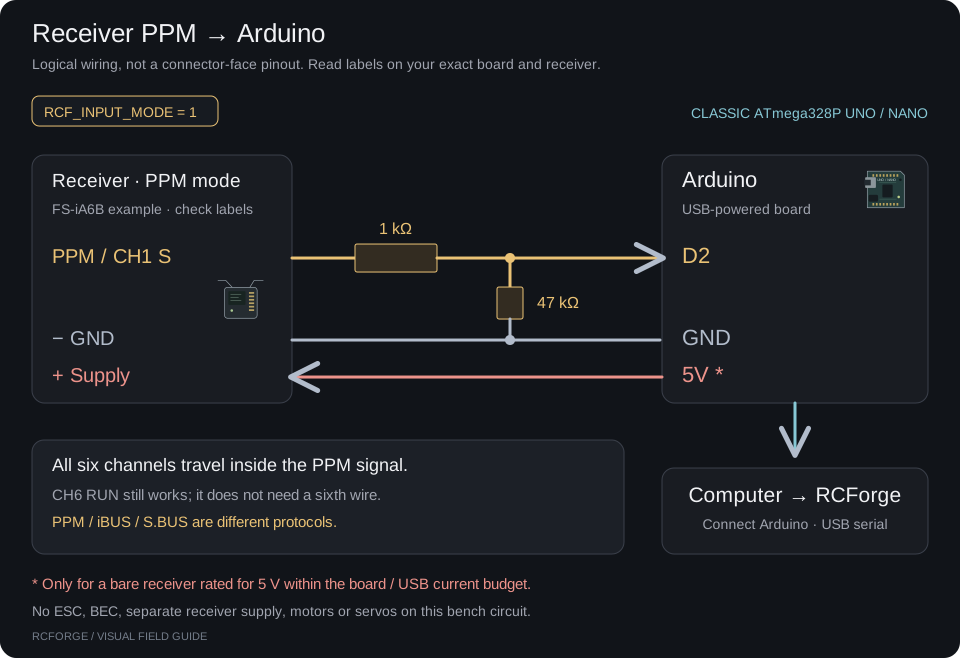
Reconnect USB only after checking every label and joint. Keep D0/RX and D1/TX free.
6. Set up the simulator model on the FS-i6#
Use a spare airplane model named RCForge. Leave transmitter elevon, V-tail, custom mixes, trainer/student mode and throttle hold disabled. Start with centered trims/subtrims and normal rates; RCForge applies aircraft-specific mixing.
With the receiver connected:
- System setup → RX setup → PPM Output: enable PPM; hold CANCEL to save.
- Functions setup → Aux. channels: assign CH6 → SwD; hold CANCEL to save. Reserve CH5 for an optional simulator function.
- For Mode 2, left vertical is throttle, left horizontal yaw, right horizontal roll, right vertical pitch. Match the radio's actual stick mode; do not change modes blindly.
These menu functions are described in FS-i6 manual §§5.5, 7.7–7.8 and 8.2. Menu wording may differ by firmware. “PPM” is the setting you need, not an i-BUS channel assignment.
What CH6 does in RCForge#
The checked-in bridge accepts input only while CH6 > 1700 µs. Call that switch position RUN; the other is STOP. Determine the direction from the values during step 8—do not assume switch up/down corresponds to high/low.
STOP means RCForge deliberately reports invalid/stopped input. It is not a start button or a motor arm command. Use the on-screen Start initially. Keep the guard enabled for this wireless receiver route.
7. Upload the existing sketch with Arduino IDE#
Open rcforge_bridge.ino. In a local checkout it is inside hardware/rcforge_bridge/. If downloaded separately, keep it in a folder called rcforge_bridge so Arduino IDE recognizes the sketch.
Near the top, retain:
#ifndef RCF_INPUT_MODE
#define RCF_INPUT_MODE 1   // PPM: one signal wire into D2
#endif
#ifndef RCF_GUARD_CHANNEL
#define RCF_GUARD_CHANNEL 6
#endif- Plug the Nano into USB. In IDE Boards Manager, install Arduino AVR Boards if absent.
- Choose Tools → Board → Arduino AVR Boards → Arduino Nano.
- Choose Tools → Processor → ATmega328P.
- Select the port that appears when this Nano is plugged in. On macOS, a clone may appear as a
/dev/cu.usbserial…or/dev/cu.wchusbserial…device; the actual name varies. - Click Verify, then Upload. Wait for the IDE's successful-upload message.
- If upload cannot communicate, try ATmega328P (Old Bootloader) and upload again. If the chip is ATmega168, LGT8F or another variant, this sketch's ATmega328P requirement is not satisfied—identify the board before proceeding.
Arduino documents Nano processor/bootloader selection here. A charge-only cable, occupied serial port or missing USB-chip driver can also prevent upload; a lit LED does not resolve those possibilities.
No receiver library is required. Do not replace this sketch with a generic PPM-to-serial example: RCForge expects its specific RCF1 packets and checksum.
8. Verify the data before opening RCForge#
Open Arduino IDE Serial Monitor, select 115200 baud, then switch CH6 to RUN. The sketch emits about 50 lines/second. Lines have this structure:
RCF1,sequence,valid,PPM,6,ch1,ch2,ch3,ch4,ch5,ch6*CRCThis is a format explanation, not a packet to paste into the program.
| Observation | Meaning / next action |
|---|---|
valid becomes 1 |
All six pulses are accepted and CH6 is high. |
| Stick values change independently | The wireless link, PPM output and decoder are working together. |
| Centered sticks near 1500; ends near 1000/2000 | Expected nominal pulse scale; exact endpoints vary. |
CH6 switch changes valid to 0 |
STOP guard is working. |
valid stays 0 |
Check RUN direction, binding, PPM setting, D2 wiring and six-channel framing. |
| Channels stay centered while invalid | Intentional: the sketch substitutes inactive values for rejected input. This does not mean your sticks are mechanically centered. |
| No output at all | Check port, upload and baud rate first. |
The receiver LED shows the radio link. The Nano power LED shows board power. The sketch's built-in LED shows accepted input, but clone LED layouts differ; Serial Monitor is the clearer test.
Set receiver failsafe#
In RX setup → Failsafe, enable a stored CH6 STOP value and CH3 low throttle; use centered roll/pitch/yaw. Select each channel, enable failsafe, put its control in the desired position, then hold CANCEL to confirm; hold CANCEL again to save the menu. Off means hold the last value, not STOP. FS-i6 manual §8.4.
Bench test with the bare receiver: start in RUN, switch the transmitter off and watch valid become 0. Power the radio back on and verify recovery. If input stays valid, fix failsafe before relying on automatic radio-loss detection. This intentional radio-off test is for the receiver-only simulator setup, with no actuators connected.
9. Connect and calibrate RCForge#
Close Serial Monitor and Serial Plotter first. Only one program can own this serial port.
- Open RCForge in desktop Chrome at localhost or HTTPS. Use your local development URL, or the hosted site once deployed.
- Open Controllers → RC transmitter → Connect Arduino.
- Select the Nano's port in the browser chooser. Allow a few seconds for the board to reboot.
- Radio on, receiver linked, CH6 in RUN: expect Live transmitter input.
- Select the Arduino/serial device if it is not automatically selected. Do not choose Find USB adapter for this route.
- Use Detect to identify each input; the initial channel order is below.
- Capture neutral with pitch/roll/yaw released, sweep full travel, save calibration, then check throttle spans 0–100%. Do not center the throttle as if it were a spring-return axis.
| Radio channel | RCForge function | Mode 2 control |
|---|---|---|
| CH1 | Roll | Right stick left/right |
| CH2 | Pitch | Right stick forward/back |
| CH3 | Throttle | Left stick up/down |
| CH4 | Yaw | Left stick left/right |
| CH5 | Optional function | Assigned switch/knob |
| CH6 | RUN/STOP guard | SwD, as configured above |
Use Reverse when the live diagram moves opposite to your intended command. Check right roll, nose-up pitch and right yaw individually; throttle down must be 0%. RCForge's control-test view lets you inspect the simulated surfaces before flight.
The receiver has six signal channels; this does not give six independent stick axes. Four carry primary flight controls, and two carry auxiliary values. Radio menu buttons are not transmitted as gamepad buttons. Start/pause/reset can stay on-screen while you finish calibration; use the controller settings for supported auxiliary bindings afterward.
10. First flight and stop test#
- Start with the Tiny Trainer or Simple Trainer, calm wind and Gentle response.
- Use ground launch, lower throttle, set RUN and click Start flight. Raise the transmitter throttle gradually.
- Switch CH6 to STOP: flight must pause. Return to RUN and resume deliberately.
- Unplug USB: flight must pause. Reconnect, verify live controls and resume deliberately.
- Confirm the transmitter-off test also pauses flight.
- Normal shutdown: disconnect receiver/Nano USB, then turn off the transmitter.
Binding, valid serial data, calibration and radio-loss behavior are separate checkpoints. Complete them in that order.
11. If PPM will not work: six-wire PWM fallback#
The current bridge accepts exactly six PPM channels. Receiver/firmware variants that emit a different frame length can remain invalid even with good wiring. Do not disable the CH6 guard to mask that problem.
After checking the preceding steps, use the six labeled PWM outputs instead:
- Unplug USB. Disable receiver PPM in the radio; save the setting.
- Change
RCF_INPUT_MODEto 2 and upload again. - Use one 1 kΩ series resistor plus 47 kΩ pulldown per signal, and the same single power/ground connection.
Receiver signal       Series resistor      Nano
CH1 S ─────────────────[1 kΩ]────────────── D2   Roll
CH2 S ─────────────────[1 kΩ]────────────── D3   Pitch
CH3 S ─────────────────[1 kΩ]────────────── D4   Throttle
CH4 S ─────────────────[1 kΩ]────────────── D5   Yaw
CH5 S ─────────────────[1 kΩ]────────────── D6   Auxiliary
CH6 S ─────────────────[1 kΩ]────────────── D7   RUN/STOP

Each D2–D7 also has its own 47 kΩ resistor to common GND.
B/VCC + → Nano 5V.  B/VCC − → Nano GND.
All six signal wires must be present. Repeat the serial, failsafe and calibration checks; the packet mode should now say PWM.
Quick troubleshooting#
| Symptom | Check next |
|---|---|
| Receiver LED does not light | USB power, 5V/GND labels, reversed polarity, loose or unsoldered headers. |
| Receiver keeps flashing | Correct model/protocol, bind plug procedure, transmitter power; pairing may not have completed. |
| Radio appears paired but RCForge says input stopped | CH6 RUN assignment and direction, then PPM/D2 and frame format. |
| Arduino upload works but browser cannot connect | Close IDE serial windows; select Connect Arduino in a desktop Web Serial browser. |
| No serial-port chooser / disabled button | Try desktop Chrome on localhost or HTTPS; browser support differs. |
| Only one axis changes | CH1 may still be PWM, or an incorrect port/protocol is being read. |
| Two flight functions move together | Disable radio mixes; check RCForge axis assignments for duplicates. |
| Radio off but simulation stays live | Receiver is holding outputs; revisit CH6 failsafe and test again. |
| Cannot read the pin labels | Stop before power-up and take a clear close-up of the receiver pin end and both Nano sides. |
Verification limits#
The connections match the checked-in bridge, the manufacturer's documented PPM port and the classic Nano pinout. Your particular board, receiver firmware, actual voltages and physical wiring have not been tested remotely. No upload or change to your transmitter has been performed by this guide.
Additional references: general visual radio guide, full FS-i6 bridge reference, Chrome Web Serial documentation.