 RC
RCChoose a radio connection#
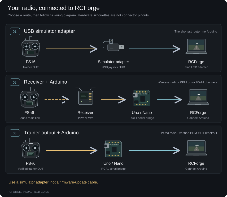
Choose a path, follow its wiring, then verify the controls. These diagrams describe the original FlySky FS-i6 and classic ATmega328P Uno R3 / Nano. Other receivers, boards and cable pinouts need their own checks.
| Your hardware | Start here |
|---|---|
| Compatible USB simulator joystick adapter | USB adapter — no Arduino |
| Bound receiver with PPM output | Receiver PPM — one signal wire |
| Bound receiver with CH1–CH6 PWM outputs | Receiver PWM — six signal wires |
| Documented trainer PPM OUT breakout | Trainer PPM — wired to the radio |
Need help with your exact parts? Configure a prompt for your coding agent. The detailed FS-i6 reference includes troubleshooting and protocol details.
Have an FS-i6 and Nano? Start with the direct trainer walkthrough. The receiver bench procedure covers binding and wiring, but receiver connections are still to be tested successfully.
Connection test status#
| Route | Evidence and remaining checks |
|---|---|
| FS-i6 trainer → Nano | User-supplied diagnostic output shows six-channel PPM and changing stick values; CH6 RUN was reported. Full RCForge calibration and signal-loss/recovery are not yet confirmed. |
| FS-iA6B receiver → Nano (PPM) | Still to be tested successfully. An attempted bench connection caused the USB port to disappear when the transmitter linked. The cause is unresolved; do not describe this route as hardware-validated. |
| Receiver → Uno/Nano (six PWM wires) | Still to be tested on hardware. Firmware compilation is not a physical connection test. |
| USB simulator adapter | Documented option; no adapter hardware test is recorded here. |
The sketches compile for classic Uno/Nano. The trainer evidence does not validate receiver power, binding or RF failsafe. Start with the trainer walkthrough for the connection demonstrated so far.
1. USB joystick adapter#
Use an adapter documented for the FS-i6 trainer output that presents itself as a USB joystick. A firmware-update cable will not work for this route.
- Power the FS-i6 from its own batteries. Connect its trainer output to the adapter, then plug the adapter into USB.
- Follow the adapter's trainer/student-mode instructions. Create a dedicated simulator model without elevon/V-tail mixing.
- Open Controllers → RC transmitter → Find USB adapter, select the device and calibrate.
No sketch is required. Only switches actually exposed by the adapter can become simulator shortcuts; the FS-i6 menu buttons are not sent over the radio.
2. Receiver PPM#
Use a separate, bound receiver on the bench. The FS-iA6B is one example with PPM output and a documented supply range that includes 5 V. In the FS-i6's RX setup → PPM Output, select PPM and hold CANCEL to save. This changes CH1 from a single PWM channel to the combined PPM signal; confirm your receiver's labels. FS-i6 manual, §8.2.
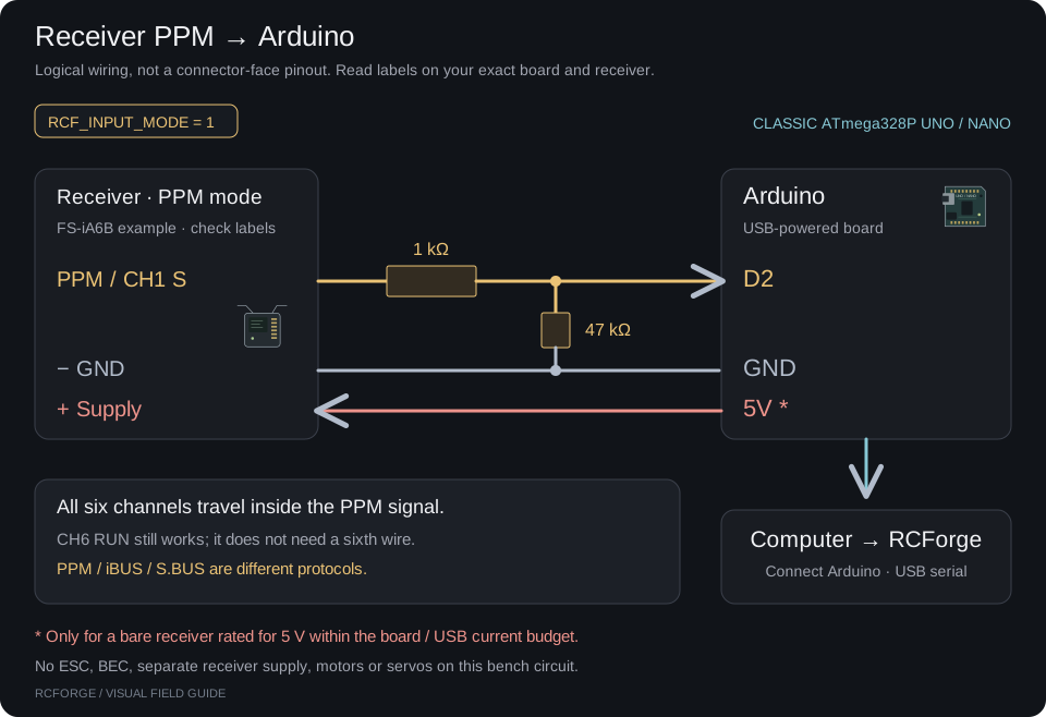
- S / PPM → 1 kΩ → D2, with 47 kΩ from D2 to GND.
- Receiver − → GND. Receiver + → 5V only under the supply conditions shown.
- Select
RCF_INPUT_MODE 1. All six channels, including the CH6 RUN guard, travel over the single PPM signal.
A port marked iBUS, SENS or S.BUS is not PPM. The current sketch reads PPM or PWM; it does not decode those other protocols.
3. Receiver PWM#
Use CH1–CH6 servo outputs and disable PPM output if it was enabled. Every signal needs its own resistor pair. All six channels must be present.
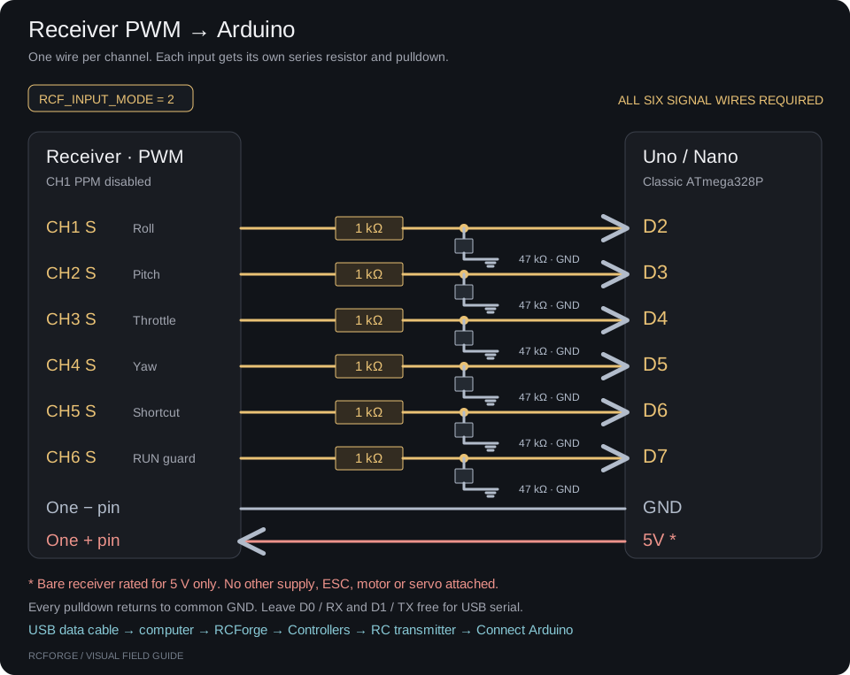
| Receiver signal | Arduino pin | Initial function |
|---|---|---|
| CH1 S | D2 | Roll |
| CH2 S | D3 | Pitch |
| CH3 S | D4 | Throttle |
| CH4 S | D5 | Yaw |
| CH5 S | D6 | Optional shortcut |
| CH6 S | D7 | RUN / receiver failsafe |
Select RCF_INPUT_MODE 2. Join one receiver − to Arduino GND and use the
same bare-receiver power conditions as the PPM route. Leave D0/RX and D1/TX free.
4. Trainer PPM#
See the rear-socket drawing and Nano diagnostic walkthrough for a closer view and a sketch that displays the incoming channels.
This route connects the transmitter directly to the Arduino. Start with a breakout whose PPM OUT and GND contacts are documented for your exact FS-i6 cable. The drawing uses signal names, not guessed DIN pin numbers or wire colors.
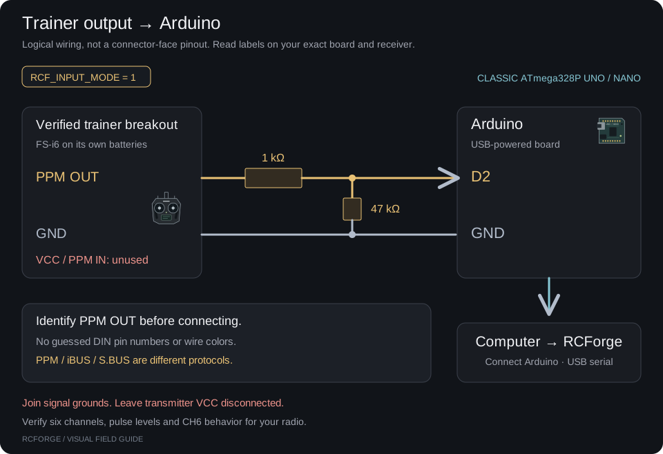
Select RCF_INPUT_MODE 1. Leave VCC and PPM IN disconnected. The transmitter
uses its own batteries; USB powers the Arduino. Confirm six-channel PPM output and
which physical control becomes CH6, especially in student mode. If the pinout is
unknown, use a labeled receiver output or a documented simulator adapter.
See the trainer limitations, including the
narrow wired-only exception when CH6 is unavailable.
Build each input circuit#
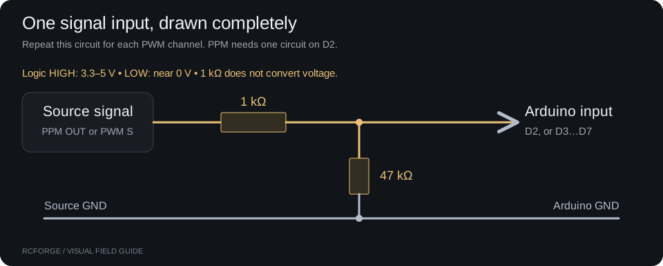
Use one circuit for PPM or six for PWM. The 47 kΩ resistor connects after the 1 kΩ resistor, at the Arduino input. Signal HIGH must be 3.3–5 V, LOW near 0 V. A resistor does not convert higher or negative voltages.
For a USB-powered bench receiver, verify that its supply rating includes 5 V and its current fits the board/USB budget. The FS-iA6B is rated 4.0–8.4 V. Connect no ESC, BEC, other supply, motors or servos to this circuit. FlySky receiver specifications.
Can I use another Arduino?#
Yes—the bridge does not have to be a classic Uno or Nano. Its job is to read the radio's PPM pulses and send channel values in a format RCForge understands. Another Arduino or microcontroller can do this if it supports suitable signal capture and USB serial, with firmware adapted to that board.
Transmitter PPM OUT ──→ compatible input pin
Transmitter GND ─────→ board GND
                          │
                  Arduino / microcontroller
                  Decode pulses → RCF1 packets
                          │ USB serial
                          ▼
               RCForge → Connect Arduino
The important distinction is compatible hardware versus ready-to-upload firmware:
| Board / route | What you need |
|---|---|
| Classic ATmega328P Uno R3 or Nano | The included sketch; use the wiring and board selection below. |
| Other Arduino boards, including Leonardo, Uno R4, Nano Every or 3.3 V boards | A board-specific port of the bridge. Adapt interrupt/timer code, input pins and serial setup; check electrical levels. These boards are not covered by the supplied sketch's compile checks. |
| Board running USB joystick firmware | Use Find USB adapter, provided it enumerates as a compatible gamepad. This is a different firmware/USB route. |
For Connect Arduino, printing raw channel numbers is not enough. Send the documented RCF1 serial protocol: channel widths, sequence number, input-valid status and CRC checksum at 115200 baud. Preserve the CH6 RUN/STOP guard and signal-loss detection. A new bridge must stop reporting valid input when its signal is lost.
Do not copy the classic Nano's D2 wiring to another board without checking its pinout and interrupt support. A 3.3 V board may require level conversion; the illustrated resistors alone are not a level shifter. Power the board from USB for the trainer route, share ground, and leave the transmitter's power contacts unused. Verify the exact board's Arduino documentation and interrupt-capable pins.
Receiver PPM/PWM connections remain unverified on the reported setup. Supporting another board in code does not establish a physical wiring or flight test.
Load the bridge and connect#
Download the version-matched RCForge bridge sketch,
or open it in your cloned project. Keep the file inside a folder named rcforge_bridge.
- In Arduino IDE, set
RCF_INPUT_MODEto 1 for PPM or 2 for PWM. KeepRCF_GUARD_CHANNEL 6. - Select Arduino AVR Boards → Arduino Uno or Arduino Nano → ATmega328P and your board's USB port. Upload using a USB data cable.
- Close Serial Monitor. In desktop Chrome, open RCForge on localhost or HTTPS.
- Choose Controllers → RC transmitter → Connect Arduino, select the serial port, and allow the board to reboot.
Classic Nano clones may need ATmega328P (Old Bootloader). This sketch is not for Uno R4 or Nano Every. It sends USB serial into RCForge, not a system-wide USB joystick. Uno R3, classic Nano, Web Serial.
Verify RUN, then calibrate#
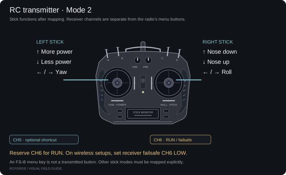
For receiver routes, assign CH6 to a two-position switch: high is RUN, low is STOP. Set receiver failsafe CH6 low, throttle low and centered controls. In the FS-i6 failsafe menu, Off means hold the last output, which will not reliably signal a lost radio link. FS-i6 manual, §8.4.
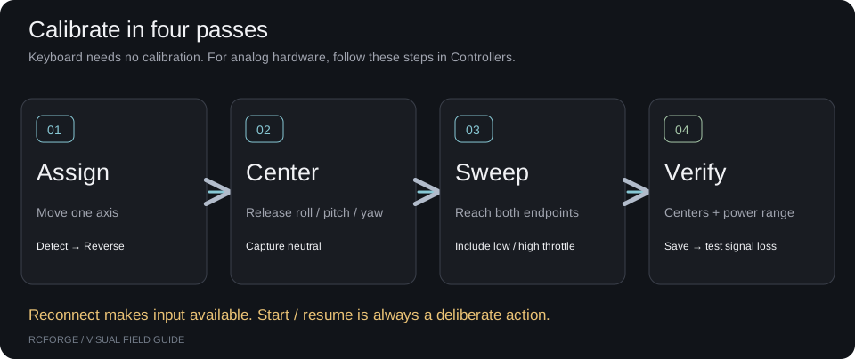
- In RUN, verify four independent controls. Use Detect and Reverse as needed, then capture neutral and full travel.
- Save and check centered roll/pitch/yaw and 0–100% throttle. Lower throttle before starting.
- For receiver routes, turn the transmitter off: live input must stop and flight must pause. If it stays live, fix receiver failsafe before relying on it.
- Verify signal removal and USB removal also pause flight. Reconnect, check the controls, and resume deliberately.
The drawings and pin assignments are checked against the sketch and manufacturer references. Physical wiring, USB drivers and your receiver's failsafe still need bench verification. No connected hardware is claimed by these guides.
Set up with an AI agent#
Fill in your hardware on the website, then Copy prompt. In the Markdown file,
replace the {{…}} fields yourself. Paste it into your coding agent inside an
RCForge checkout. The agent can inspect code and prepare board-specific commands;
you make the physical connections and operate the radio.
Fill in what you know. This stays in your browser; copy it into your preferred coding agent.
Preview prompt
Help me connect my RC controller to RCForge in this checkout.

Connection route: {{Connection route|Receiver PPM|Receiver PWM (six channels)|Trainer PPM|USB joystick adapter}}
Board: {{Arduino board|Uno R3 (ATmega328P)|Classic Nano (ATmega328P)|Classic Nano (Old Bootloader)|None — USB joystick adapter|Other or unsure}}
Transmitter: {{Transmitter model and firmware}}
Receiver or adapter: {{Receiver or adapter model}}
Computer: {{Operating system and browser}}
Cable / breakout information: {{Cable labels or pinout link}}

Read AGENTS.md, docs/radio-setup.md, docs/flysky-fs-i6.md and hardware/rcforge_bridge/rcforge_bridge.ino first. Treat the current checked-out firmware as authoritative. Ask for missing model names, clear connector photos or manufacturer pinouts. Never guess DIN pin numbers from wire colors or assume a USB programming cable is a joystick adapter.

For my chosen route, produce a labeled connection table with source pin, resistor, board pin, common ground and power arrangement. For the supplied classic ATmega328P sketch, PPM uses D2 and six-channel PWM uses CH1–CH6 to D2–D7. For another board, verify its pinout and port the input capture and USB serial code while preserving the RCF1 protocol, guard and signal-loss behavior. Each input needs 1 kΩ in series and 47 kΩ to ground on the Arduino side. Verify signal voltage and receiver supply requirements from primary sources. Do not join USB 5 V to an ESC/BEC or another supply. Use a bare bench receiver without motors or servos.

For Arduino, prepare exact compile commands for my board and input mode, keeping CH6 RUN guard enabled on receiver routes. Classic Nano bootloaders differ. Use the existing RCF1 bridge; do not replace it with a generic serial sketch. List ports, but do not choose a port or upload without my explicit selection and instruction. For a USB joystick adapter, skip firmware and explain Find USB adapter instead of Connect Arduino. If my board or protocol is unsupported, explain that before proposing changes.

Guide me through radio setup with simulator mixing disabled, CH6 high RUN / low STOP, receiver failsafe CH6 low and throttle low. Do not disable the guard to hide missing input. Then guide mapping, reversal, neutral/endpoints, low throttle, signal/USB loss and radio-off tests. Reconnection must require deliberate resume. Separate code/compile results from physical checks that only I can confirm. Finish with the exact wiring, configuration and unresolved checks for my setup.